18. Allocating Responsibility for Delays
Key Words and Concepts
- Work activities
- Dependency ties
- As-built network
- As-planned network
- Schedule update network
- Owner responsibility delays / Contractor responsibility delays
- Discrete events
- Burden of performance
- Excusable delays
- Incorporation of delays into network
- Forward-looking analysis
- Retrospective analysis
- Intermediate impact analysis
- Concurrent delay
- Four principles governing delay impact analysis
- Delay analysis for single-path projects
- Delay analysis for multi-path (concurrent path) projects
- Delay impact analysis for complex projects with several interconnected concurrent paths
- Float time
- Owner liability for delay damages
- Contractor-caused delay
- Contractor liability for liquidated damages
- Contractor entitlement to an extension of time
- Damages offset not necessarily day-for-day
This chapter explains the principles and procedure by which contractor liability for liquidated or actual damages and owner liability for monetary damages for owner-caused delay are determined in practice. Delays usually occur during performance of the typical contract, some within the control of the contractor, some caused by the owner or for which the owner is otherwise liable, and some that are beyond the control of either party, for which neither party is liable. All three commonly occur at various times, generally affecting only one part of the project, although some may affect the entire project.
When the owner and contractor disagree on questions of extensions of time, liquidated damages, or owner-caused delay damages, the first problem facing courts and other dispute resolution bodies is determining delay responsibility. Once the individual delays and the party responsible for them have been identified, the second problem is determining the consequences of the delay(s). This latter problem is usually solved by performance of a critical path method (CPM) schedule delay impact analysis. The principles and procedure for performing such an analysis follow.
Preliminary Points and Definitions
Construction contracts today commonly provide that the performance of the work be planned and monitored by the use of the critical path method. The contractor is required to submit a CPM network schedule that depicts the construction work activity sequence and the beginning and ending dates of all work activities as the contractor intends to perform them. Such an initial schedule is often referred to as the baseline schedule. As the work progresses, the contractor is usually required to update the baseline schedule periodically (monthly or quarterly), reflecting the actual beginning and ending dates for all completed work activities, the actual start and estimated completion dates for all activities in progress, and the anticipated start and end dates for all remaining work activities. Such schedules provide a convenient method by which the impact of delays can be determined. (If you are not familiar with the CPM scheduling method, refer to any of the numerous available texts on that subject for details.) In the following discussion, only general concepts will be presented to illustrate the methods of delay impact analysis.
As-Planned, As-Built, and Schedule Update Networks
A CPM network is a graphic depiction in which the various physical work items of the project are represented as a sequential arrangement of work activities joined together by dependency ties. The dependency ties indicate the sequence in which the activities must be performed as well as the requirement that immediately preceding activities must be completed prior to the start of following activities on the same path of work or to the start of following activities on parallel paths of work.
For instance, consider the simplified generic CPM network schedule illustrated by Figure 18-1 in which contract work activities are represented as time-scaled solid arrows A, B, C, D, E, F, G, and H. The time duration of each in months is indicated directly above each work activity arrow.
Such a CPM network schedule implies that the following logic discipline be maintained:
- Along each line of consecutive work activity arrows, each predecessor work activity must be completed before the successor work activity can commence.
- The dependency ties that exist between separated work activity arrows are established by the dotted lines between the work activity arrows, either those included in a line of separated arrows such as between work activities C and D and between work activities G and H, or between work activity arrows on parallel lines such as between work activities A and E, F and D, and between work activities D and H.
- The direction of the arrowhead included in dependency ties determines which of the connected work activities is the precedent activity and which is the successor activity that cannot start until the completion of its predecessor. In Figure 18-1, work activity E cannot start until work activity A has been completed, work activity D cannot start until work activities C and F have been completed, and work activity H cannot start until work activities D and G have been completed.
- The time duration that the completion of work activities could be delayed without delaying the completion of the project is termed float time. In Figure 18-1, work activities Band C together have 2 months of float and work activity G has 3 months of float.
- Early start and early finish dates are the earliest possible points in time that a work activity can start and finish, while late start and late finish dates are the latest points in time that a work activity can start and finish without delaying the completion of the project. For instance, the early and late start dates for work activity B would be 3 months and 5 months after NTP and 8 months and 10 months after NTP, respectively, while early and late start dates for work activity C would be 8 months and 10months after NTP, and 10months and 12 months after NTP, respectively. Similarly, early and late start dates for work activity G would be 12 and 15 months after NTP, and 16 and 19 months after NTP, respectively.
- The critical path is a path of work activities that contains no float and thus controls the completion date of the project. In Figure 18-1, the sequence of work activities A, E, F, D, and H is the critical path. Some networks may contain more than one critical path.
- Early and late start dates and early and late finish dates are the same points in time for work activities on the critical path (i.e., activities that contain no float).
When a network schedule such as Figure 18-1 is created before the commencement of project work as a planning tool, or is submitted to the owner by the contractor before contract work in compliance with project specification scheduling requirements, it is referred to as an as-planned or baseline schedule network reflecting the contractor’s plan for the accomplishment of the work. As the work progresses, such a schedule is monitored by periodically updating it to reflect the completion status of the project at the points in time of the periodic updates. Such a network would be referred to as a schedule update network.
For instance, if the generic schedule network shown in Figure 18-1 had been submitted by a contractor as the as-planned or baseline schedule, the schedule update after seven months of contract performance might look as indicated in Figure 18-2. Such an update schedule reflects actual as-built performance up to the date of the update documented by project records and as-planned performance for the balance of the work to project completion. At the time of the update in this hypothetical illustration, activity A had been completed and activities B and E partially completed. The completion dates for activities B and E necessarily would have to be estimated based on experience to date while the balance of the work is shown in accordance with the baseline schedule indicating the contractor’s belief that, in spite of a slow start, the balance of the work will be accomplished in accordance with the original plan. The updated schedule network shown in Figure 18-2 indicates that at the time of the update, the contractor was two months behind the baseline schedule. Subsequent periodic schedule updates as the work progressed would normally be carried out until the project was completed, each update regularly reflecting as-built performance up to the date of the update and as-planned performance thereafter to project completion.
A final update made at the point in time of project completion would reflect total as-built performance as documented in project records. Such an as-built network for the project represented by Figures 18-1 and 18-2 could well tum out as indicated in Figure 18-3. By improving performance in the completion of activity B and for all of activities D, F, and H, the contractor in this hypothetical example regained time and completed the project one month earlier than the 25-month completion time of the baseline schedule.
It should be noted that the hypothetical schedule networks shown in Figures 18-1, 18-2, and 18-3 are simple generic networks utilized here for purposes of illustration only. Actual project schedule networks are normally far more complex and contain many more work activities and dependency ties as well as numerous paths to project completion.
Owner Responsibility Delays
Delays or extensions of work activity performance exclusively caused by the owner or otherwise the contractual responsibility of the owner are compensable delays. These kind of delays entitle the contractor to additional payment for any costs incurred as a result of the delays. The contractor is also entitled to an extension of contract performance time if the delays cause the overall project performance duration to be extended. For purposes of identification of this class of delay, the symbol “ORD” (owner responsibility delay) is used in the schedule networks that follow in this chapter.
Contractor Responsibility Delays
If the total time allowed for contract completion is exceeded, delays or extensions of work activity performance that are exclusively the fault of the contractor or otherwise the contractual responsibility of the contractor do not entitle the contractor to extra compensation or an extension of contract performance time and may result in the contractor becoming liable for the payment of liquidated damages. For purposes of the analysis in this chapter, this class of delay must be subdivided into two subclasses:
- The first subclass consists of delays that can be easily recognized as discrete events or happenings. Examples would be clearly identified contract breaches such as failure to make required submittals by contractually stipulated dates or any other identified delay caused by or the contractual responsibility of the contractor including subcontractors and suppliers. For purposes of identification in the networks that follow, the symbol “CRD” (contractor responsibility delay) will be used for this subclass of contractor responsibility delay.
- The second subclass arises from the contractor’s failure to perform the actual work items of the contract at a rate sufficient to complete the contract on time. This subclass of contractor delay is not directly identified by a symbol on the network schedules that follow. The contractor’s burden of performance is to complete all of the contract work in accordance with the requirements of the technical specifications within the time limits specified in the contract. To meet this burden, the contractor is free to choose the means, methods, techniques, sequences, and procedures of accomplishing the work. Contractor failure to meet the burden of performance, unless interfered with or delayed by others, may entitle the owner to liquidated damages-or actual provable damages in contracts that do not contain a liquidated damages provision. However, the contractor’s failure to accomplish a given item of work (i.e., a work activity) within the time limits of an as-planned or intended project schedule does not in and of itself mean that the contractor has failed to meet the burden of performance or has incurred liability to pay damages. Unless the contract contains explicit language to the contrary, the contractor is free to make up for such lost time by performing later work activities at a rate faster than the as-planned or originally intended rate that may have been depicted on the as-planned schedule or on any other form of contractor-produced project schedule. Only when the required work of the entire contract has been completed, or the required work for a given milestone has been completed in the case of milestone completion date contracts, is it possible to determine whether the contractor has satisfactorily met the burden of performance.
Excusable Delays
Delays that are not the fault of either the owner or contractor are excusable delays (ED). If they result in the project duration being extended, EDs entitle the contractor to an extension of time only. The most common examples are force majeure conditions such as acts of God, war, riot, and so on.
Incorporation of Delays into the CPM Network for Delay Impact Analysis
The previously explained classes of delays or extension of work activity performance include:
- Owner responsibility delays (ORDs)
- Discrete event contractor delays (CRDs)
- Slow-work-performance contractor delays (not directly identified by a symbol)
- Excusable delays (EDs)
If the starting dates of particular project work activities shown on a schedule network have been delayed by ORDs, CRDs, or EDs, each delaying event can be identified, both as to the point in time at which it occurred (just before the start of the affected work activity) and as to its duration (the time duration of the delay). Also, some ORDs do not delay the start of a contractor work activity but rather take the form of extending the work activity to a longer duration than would have been the case without the delay. (An example of this kind of ORD would be the improper imposition by the owner’s engineer of a requirement that was not included in the project specifications that increased the time required for a work activity to be performed.) In these cases, an estimate can be made for the additional time the work activity was improperly extended. This time duration can be identified as a ORD and extracted from the duration of the affected work activity. Such a delay would be arbitrarily shown in the network to have occurred at the end of the shortened work activity (just before the start of the following work activity), even though in actuality the delaying effect was uniformly experienced throughout the work activity.
By these procedures, all of the above described delay types that may have affected the contractor work performance activities represented in a CPM schedule network can be identified and depicted in the network as discrete delay activities, each with its own duration positioned in the network at the point in time at which it is considered to have occurred.
Identifying and depicting each of the various kinds of delays as discrete activities in the network is the first step in CPM schedule delay impact analysis.
Forward-Looking and Retrospective Impact Analysis
If known or anticipated delays are inserted as discrete activities in an as-planned schedule and a delay impact analysis is performed to determine their impact on job completion, the analysis is referred to as a forward-looking delay impact analysis. This method of analysis is similar to forward-pricing a monetary claim.
On the other hand, if all project delays are inserted into an as-built network after all project work has been completed, the analysis is a retrospective delay impact analysis (akin to retrospectively pricing a monetary claim).
Some contract delay analysts believe that the impacts of delays should be analyzed when they occur and appropriate time and cost adjustments made to the contract progressively as the project work proceeds. If this is done, each delay is inserted into the updated schedule in effect when the delay occurs and a contemporaneous impact analysis is performed on a part as-built, part as-planned schedule to determine the impact of that delay.
There are arguments for and against all three approaches to delay impact analysis that are beyond the intended scope of this book. However, the principles underlying all of them are essentially the same. Once the delays have been inserted into the CPM schedule, whichever one of the three approaches is used, the analytical procedure is similar. Therefore the principles and procedures that follow, which are illustrated by application to an as-built schedule, are equally applicable to any CPM delay impact analysis, whenever performed.
Consecutive and Concurrent Events
A series of events, whether work activities or delays inserted into a network, are said to be consecutive if they follow along the same path of the network one after the other. For instance, work activities A, B, C, and D, as well as work activities E, F, G, and H, in Figure 18-1 are consecutive activities. When the events occur on separate parallel paths of the network, they are said to be concurrent events. Concurrent events may or may not occur within the same time frame. The fact that they occur on separate paths to project completion is what makes them concurrent. In Figure 18-1, work activities B, C, and D are concurrent with work activities E, F, and G.
Four Principles Governing Delay Impact Analysis
As stated previously, the starting point in determining either the number of calendar days of liquidated damages due the owner, or the number of days of compensatory delay damages due the contractor in a complex delay analysis situation, is identifying each delay as an ORD, CRD, or ED delay and inserting each into the CPM network as a discrete activity where each occurred. Once this step has been accomplished, the concept of concurrent delay must be considered.
Concurrent delay means delay to project completion that results from a number of individual delays, one or more of them occurring on a particular path to project completion and the others occurring on concurrent or parallel paths. In this situation, each of the delays may or may not have a contributory effect on project completion. Because of this, consideration of the following four principles is necessary to allocate liability between owner and contractor:
- First Principle: An owner cannot properly assess liquidated damages (LD) for periods of time during which the owner was concurrently delaying the project. In other words, the contractor can properly be assessed liquidated damages for only that part of any delay to completion of the project that was exclusively caused by or was exclusively the contractual responsibility of the contractor.
- Second Principle: A contractor cannot properly be paid delay damages (DD) for periods of time when the contractor and/or excusable delays were concurrently delaying completion of the project. In other words, the contractor can be properly paid delay damages for only that part of the total project completion delay that was exclusively caused by, or was exclusively the contractual responsibility of, the owner.
The following cases illustrate the application of the first and second principles. In one case, the government delayed completion of a floodgate rehabilitation project by delivering faulty government-furnished equipment to the contractor. However, during the final months of work, the contractor fell behind schedule with the project’s electrical work. The Engineer Board of Contractor Appeals found the two problems to be intertwined, each exacerbating the other, and refused to allow the government to withhold liquidated damages—but the board also denied the contractor recovery of delay damages.[1]
In another decision, the Veterans Administration Board of Contract Appeals similarly ruled that where government-cost and contractor-cost delays are so intertwined that they cannot be segregated, the government may not recover liquidated damages, and the contractor may not recover delay damages. In a contract for the demolition of various structures and construction of new buildings and facilities, the contractor’s slow progress and need to perform rework activities delayed completion of a boiler plant. On the other hand, the Veterans Administration’s slow response to a differing site condition and failure to coordinate the work of a separate contractor delayed completion of the paving and utility work. In total, the contract was completed 241 days behind schedule.
When the Veterans Administration withheld $282,452 in liquidated damages, the contractor filed a claim for a time extension and more than $1.6 million in delay damages. Both the government and contractor alleged that the other’s delay had been on the CPM schedule’s critical path, thus causing the late completion of the overall project. In rejecting both parties’ as-built CPM schedules, the board stated:
We find both parties have failed with regard to their attempts to establish that one or the other’s delay was solely on some mythical critical path and, therefore, was the sole cause of the delay to the contract. The project did not consist solely of the boiler plant, nor did it consist solely of final paving and electrical services…. Given the intertwined causes of delay to the project, we leave the parties where we find them. Accordingly, the government is not entitled to liquidated damages, nor is the contractor entitled to compensation for delay damages.[2]
However, case law has clearly established that when delays attributable to the owner and contractor can be separately identified and quantified, costs of compensable delay and liquidated damages can be recovered. In a 1986 decision, the Interior Board of Contract Appeals ruled that the contractor renovating a building at the U.S. Merchant Marine Academy could recover costs for delays that were identified as caused by the government. The project was plagued by a variety of delays, but the board determined that the contractor had properly segregated periods of contractor-caused delay and concurrent delay from periods of government-caused delay.[3]
Similarly, in a 1990 decision, the Postal Service Board of Contract Appeals held that when contractor-caused delays can be segregated from owner-caused delays, the contractor is entitled to recovery for the compensable portion of the delay. The contract called for substantial completion of a post office building and associated site improvements within 300 days of notice to proceed. The contracting officer complained repeatedly to the contractor about inadequate worker supply and slow progress. However, municipal officials then altered the required grades for paving and curb work, necessitating a change order from the Postal Service. The Postal Service was slow to issue the change order, bringing the contract work to a complete standstill. The project was completed well behind schedule. When both parties claimed that delay by the other had contributed to the late completion, the board agreed but said that fact did not preclude the contractor’s recovery for owner-caused delay. When periods of owner-caused delays can be segregated from periods of contractor-caused delays and the resulting costs can be separately identified and documented, the contractor can recover for periods of delay solely caused by the owner.[4]
The next principle to be considered in dealing with concurrent delay establishes the basis for segregating the exclusive effect of owner-caused delays on overall project completion from the exclusive effect of contractor-caused delays.
- Third Principle: To determine the exclusive effect on overall project completion of any one class of delays that have been identified on an as-built schedule, or on the as-built portion of an updated schedule, it is necessary to collapse the schedule on which that class of delays has been identified by removing that class of delays and reconstituting the schedule as a collapsed schedule. The effect of the removed class of delays is the difference in the completion date of the collapsed schedule from the completion date of the original schedule.
A corollary application of this principle in reverse can be stated as follows when a forward-looking delay impact analysis is made on an as-planned schedule or on the as-planned portion of an updated schedule:
- To determine the exclusive effect on overall project completion of any one class of delays, it is necessary to insert that class of delays into an as-planned schedule or into the as-planned portion of an updated schedule to reconstitute the schedule as an expanded schedule. The effect of the inserted class of delays is the difference in completion date of the expanded schedule from the completion date of the original schedule.
The fourth and final principle governs the determination of the proper time period that the contract performance time should be extended.
- Fourth Principle: The original contractually stipulated completion time plus the extension of time to which the contractor is entitled plus the contractor’s liability for liquidated damages equals the as-built project completion time.
Delay Impact Analysis for Single-Path Projects
Actual construction projects rarely if ever occur with just one consecutive path of activities from notice to proceed (NTP) to completion. However, in order to start discussion of delay impact analysis with the simplest possible case, the single-path project situation will be considered first. Figure 18-4 represents a single-path, as-built schedule.
The typical questions to be answered by the analysis are:
- What is the owner’s liability for delay damages (if any)?
- What is the contractor’s liability for liquidated damages (if any)?
- What is the contractor’s entitlement to an extension of contract time (if any)?
By inspection, the project completion date is shortened by four months if the schedule is collapsed by removing the ORD. Thus, by application of the third principle stated earlier, the effect or impact of the ORD is to increase project completion by four months for which the owner has delay damage liability to the contractor.
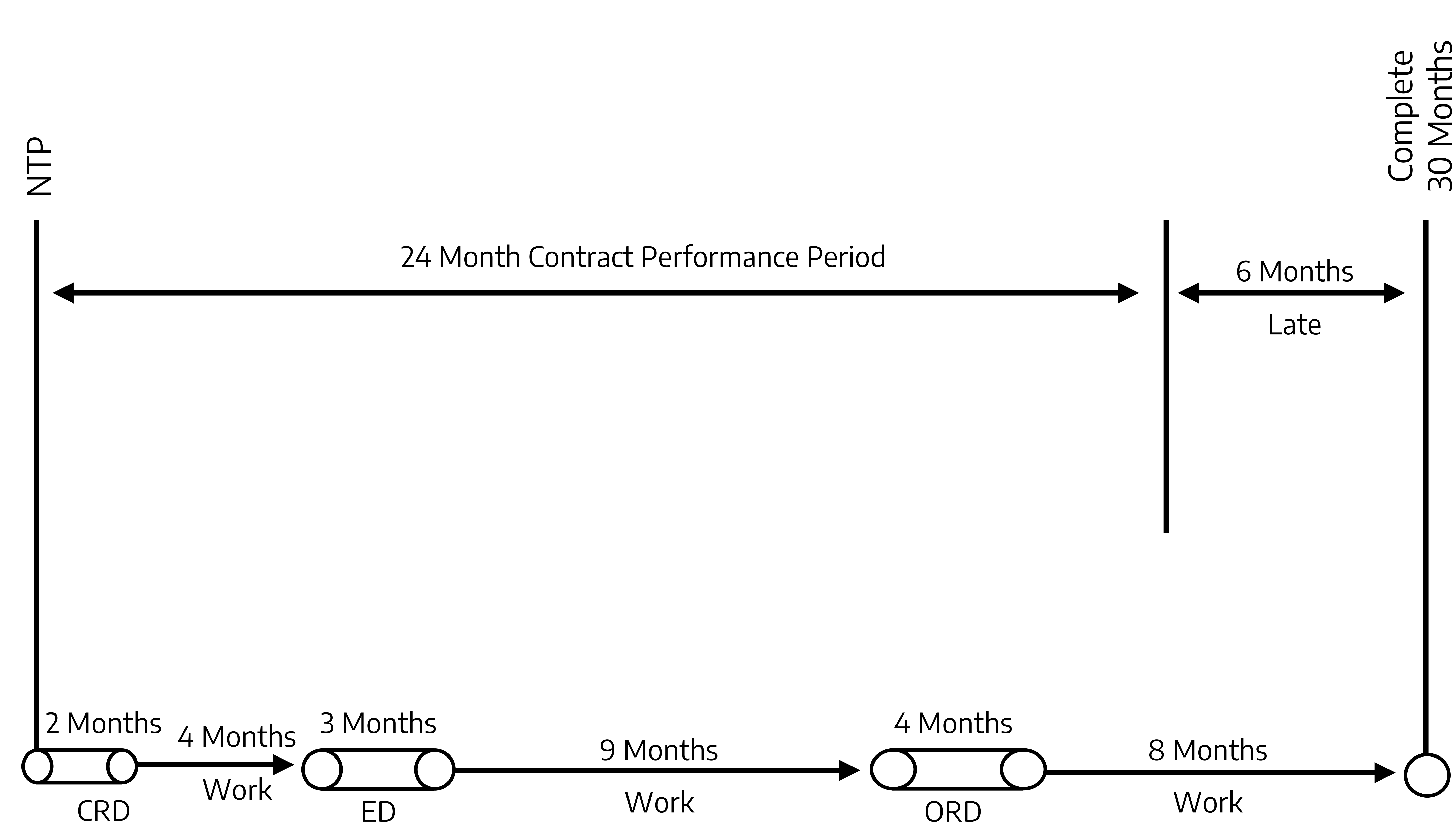
Similarly, if the schedule is collapsed by removing both the ORD and the ED (leaving only contractor-controlled activities in the schedule), project completion is shortened by seven months, and the project will be completed 23 months after NTP, meeting contract completion requirements. Thus, the contractor has met the burden of performance and has no liability for liquidated (or actual) damages. By application of the fourth principle, the contractor’s entitlement to an extension of time is determined as follows:
- Original completion time + extension of time + liability for liquidated damages = total as-built completion time.
- 24 months + extension of time + 0 = 30 months.
- Extension of time = 30 months – 24 months = 6 months.
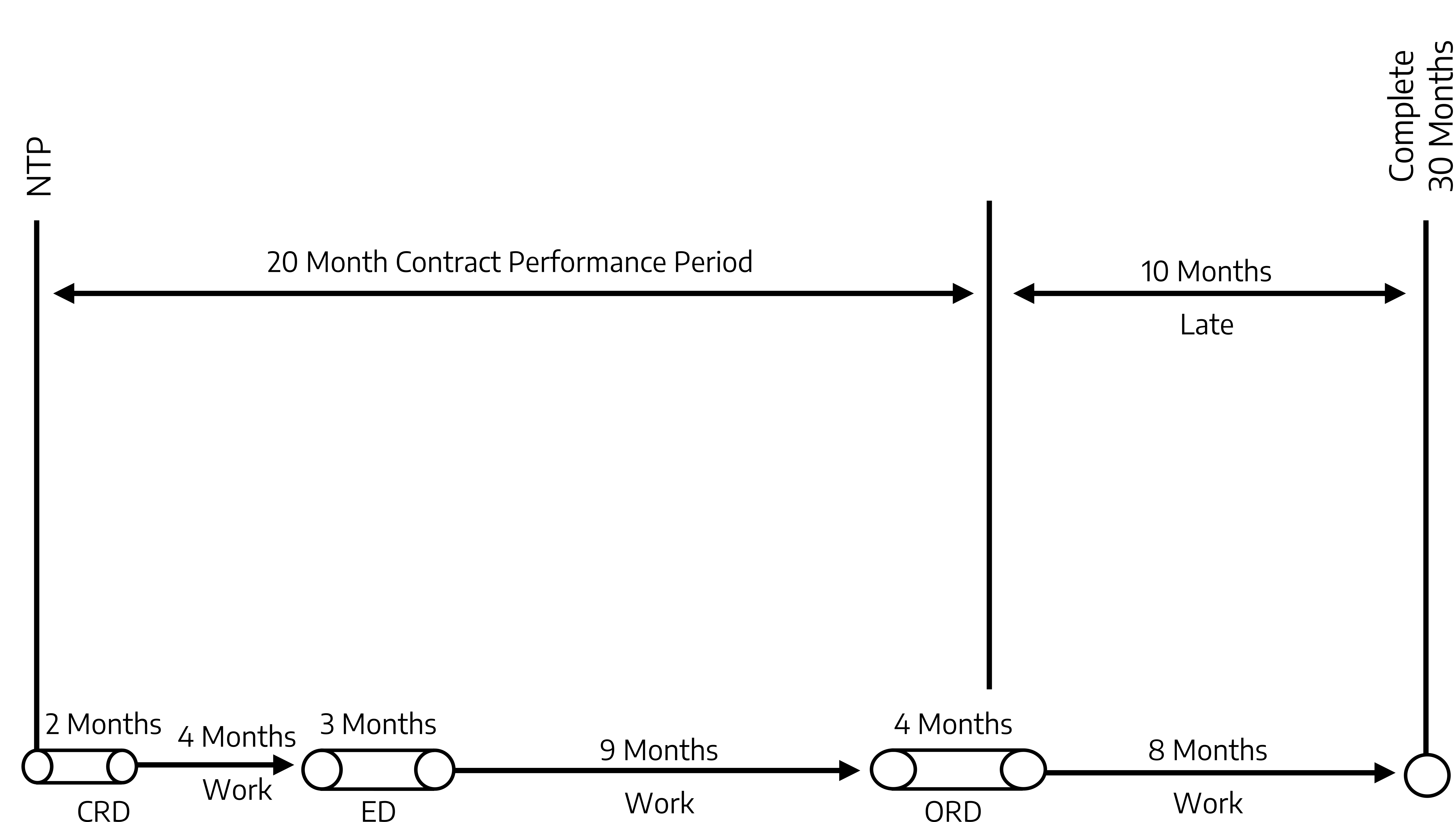
Now, assume that the contractually stipulated completion date is 20 months (instead of 24 months), resulting in the situation depicted by Figure 18-5.
The owner’s liability for delay damages does not change, remaining at four months determined, as before, by shortening the schedule when the ORD is removed. However, when both the ORD and the ED are removed, leaving only contractor-controlled activities, the schedule will collapse to a total of 23 months from NTP. If neither the ORD or ED had occurred, the contractor still would not have completed the work within the contractually stipulated performance period. Completion would have been three months late. Therefore, the contractor is subject to payment of liquidated or actual damages for the three months that actual performance extended beyond the time allowed.
Note that both subclasses of contractor delays were present in the preceding example. Even if the two-month CRD (a discrete identifiable delay) had not occurred, the contractor would still have been one month late—that is, would have failed to perform the three work activities at progress rates sufficient to meet contract time requirements.
Although perhaps overly simplistic, this example illustrates the application of the proper principles and thought processes to arrive at correct conclusions. Discussion of more complex situations follow.
Delay Impact Analysis for Multi-Path (Concurrent Path) Projects
In the preceding discussion for the second single-path project, when all ORD and ED activities were removed and the schedule collapsed, the remaining project duration consisted of activities that were entirely within the control of the contractor. In that case, since this duration exceeded the contractually stipulated project completion period, contractor-controlled delays existed, and the contractor had liquidated or actual damages liability.
In the general case, contractor-controlled delay can consist of discrete identifiable delays (CRDs), failures to complete physical work activities at a pace sufficient to meet contract time requirements, or a combination of both. Almost all construction projects are multi-path projects in which a number of separate concurrent paths of consecutive activities extend from NTP to project completion. When all ORD and ED activities are removed from a network schedule for such a project, the collapsed schedule will represent what the project duration “would have been” if the ORD and ED activities had not occurred. All remaining activities, whether CRD activities or work activities, are entirely under the control of the contractor. Under these circumstances, it might seem as if any remaining time overrun past the contractually stipulated completion date will result in liquidated or actual damages liability. This may not be true, however, because in accordance with the first principle stated earlier, the project overrun must also have been caused exclusively by the contractor—that is, there must not have been any concurrent delay to project completion that was caused by or was the responsibility of the owner or was the result of an excusable event (ED). To ensure that this condition is met prior to determining that the contractor has liability, an additional step in delay analysis is required.
Consider the multi-path project with an as-built schedule shown in Figure 18-6.
By removing the ORD activities, the as-built schedule will collapse as shown in Figure 18-7. Based on the second principle, the owner’s liability for payment of delay damages to the contractor is four months. This delay to the project completion was exclusively caused by or was otherwise the contractual responsibility of the owner.
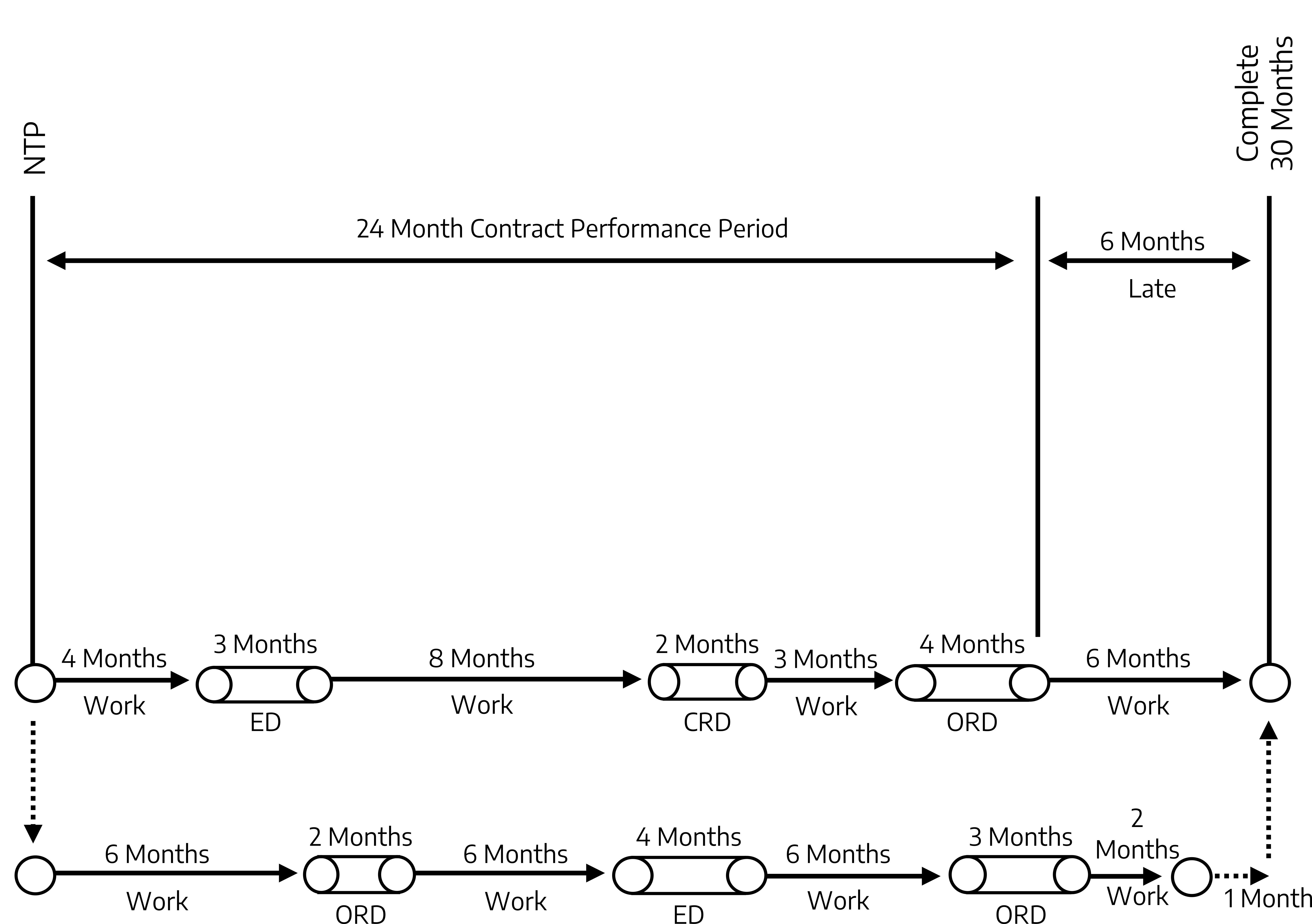
The next step in analysis is to remove the ED activities, collapsing the network further as shown in Figure 18-8. The collapsed schedule now represents a “would have been” schedule, consisting entirely of contractor-controlled activities. This schedule would have been achieved if none of the ORD or ED events had occurred. Since, by this schedule, the project is completed in 23 months (one month earlier than the contractually stipulated time), the contractor has no liability for liquidated or actual damages.
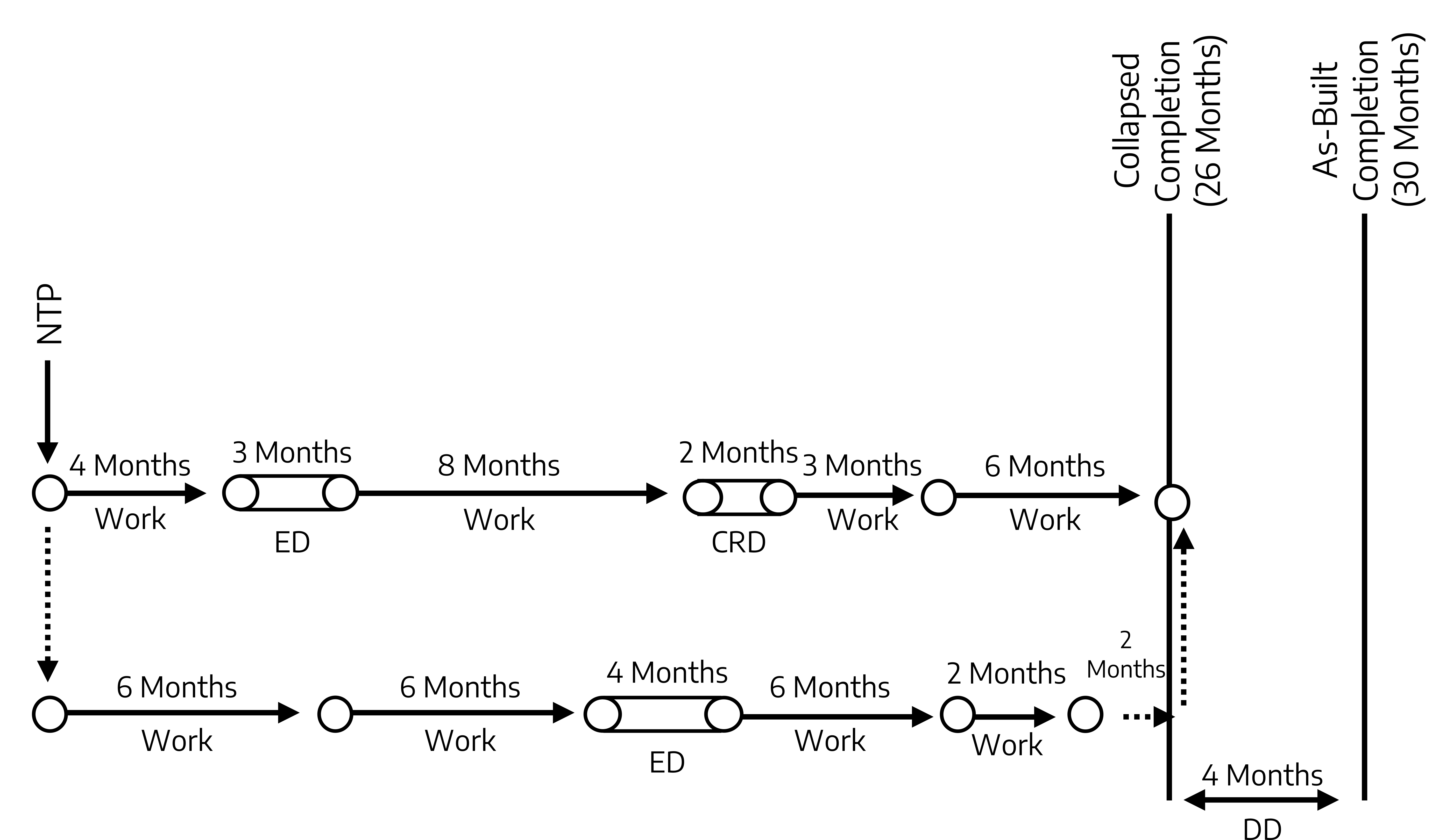
If the contractually stipulated completion period for the as-built performance shown by Figure 18-6 was 20 months rather than 24 months, all analytical steps previously taken through production of the collapsed network shown in Figure 18-8 would be the same. It is now clear that the contractor would not have met the burden of performance required by the time requirements of the contract. As Figure 18-8 shows, on the upper path, the contractor was three months late (consisting of a two-month discrete identifiable delay and one-month combined slippage in the required time performance of the four work activities on the path). On the lower path, the contractor met the burden of performance exactly by completing all activities on that path in 20 months. Even though three months late on the upper path, the contractor did not incur three months’ liability because of the first principle, stated earlier. For the contractor to incur liability for delay, the delay to the project must be exclusively caused by or the contractual responsibility of the contractor.
The three-month delay on the upper path of Figure 18-8, although caused by the contractor, did not exclusively delay the project by three months. The delay to the completion of the project that was exclusively caused by the contractor was one month only. The reasoning is as follows:
- By inspection, as-built completion on the upper path occurred 30 months after NTP.
- If the three months of contractor delay on the upper path had not occurred, the as-built completion on the path would shorten to 27 months after NTP.
- There are no contractor-controlled delays on the lower path.
- If the upper path had been shortened to 27 months after NTP, total project completion would have been determined by the length of the lower path and would have occurred 29 months after NTP.
- Therefore, the impact of all contractor-controlled delays on total project completion was 30 months less 29 months, or one month. Project completion was exclusively extended by contractor-controlled delays by only one month.
The final step in the analysis is determining the extension of time due the contractor. The reasoning follows:
- Original contractually stipulated completion + extension of time to which contractor is entitled + contractor’s liability for liquidated damages = as-built completion time.
- For the case of original contractually stipulated completion time of 24 months:
24 months + extension of time + (0) = 30 months
Extension of time = 30 months – 24 months – (0) = 6 months - For the case of original contractually stipulated completion time of 20 months:
20 months + extension of time + 1 month = 30 months
Extension of time = 30 months – 20 months – 1 month = 9 months
Delay Impact Analysis for Complex Projects with Several Interconnected Concurrent Paths
The typical construction project consists of a number of concurrent paths of activities where dependency ties exist between activities on separate paths. Such projects can be analyzed by similar procedures to those previously explained. Refer to Figures 18-9, 18-10, and 18-11.
The starting point is the representation of the as-built performance of the project constructed from project records, which results in Figure 18-9. All delays (ORD, CRD, and ED delays) are identified as activities on Figure 18-9. The dotted line durations of 110 CD, 155 CD, 70 CD, and 65 CD respectively, are float time, the length of time that the completion of the preceding activity can be delayed without delaying the completion of the project. The as-built completion time was 1385 calendar days (CD), whereas the contractually stipulated completion time was 1100 CD.
Owner Liability for Delay Damages
The first step in analysis is to remove all ORD activities from Figure 18-9, collapsing the schedule to the network shown in Figure 18-10. Note that all interpath dependency ties are maintained. Also, when collapsing the schedule, all activities are shown with the earliest possible start times (the “early” start times). Total project completion time reduces from 1385 CD to 1220 CD, establishing the owner’s liability for delay damages equal to 1385 CD-1220 CD, or 165 CD.
Has the Contractor Met the Burden of Performance?
The second step is to remove all ED activities from Figure 18-10, collapsing the schedule to the network shown on Figure 18-11. (Again note that all interpath dependency ties are maintained.) The completion time of Figure 18-11, which contains only contractor-controlled activities reduces to 1215 CD.
The third step is determining whether the contractor has performed the actual work activities at a pace sufficient to meet the contract time requirements (the burden of performance by the contractor). This must be done separately for all of the possible paths leading to completion of the project. Thus
Path ABDEFG:
30+ 150+ 30+ 300+ 460 + 40 + 175 = 1185 CD
1185 – 1100 = 85 CD longer than required time
Path CDEFG:
150 + 30 + 300 + 460 + 40 + 175 = 1155 CD
1155 – 1100 = 55 CD longer than required time
Path CHIG:
150 + 30 + 765 + 40 + 175 = 1160 CD
1160 – 1100 = 60 CD longer than required time
Path JKHIG:
30 + 175 + 30 + 765 + 40 + 175 = 1215
1215 – 1100 = 115 CD longer than required time
Path JKLM:
30 + 175 + 550 + 305 = 1060
1100 – 1060 = 40 CD longer than required time
Note that the durations of any float are not considered in making these determinations.
Clearly, the contractor did not meet the burden of performance on any path except path JKLM. The extent of contractor-caused delay on each individual path was
Path ABDEFG: 85 CD
Path CDEFG: 55 CD
Path JKHIG: 115 CD
Path JKLM: -0-
Contractor-Caused Delay to Project
The fourth step is determining the extent to which the contractor exclusively extended the completion date of the project, if any, by failing to meet the burden of performance. It is first necessary to determine to what extent the contractor-caused delay extended each of the paths to completion of the as-built schedule. This is done in accordance with the third principle by removing the exclusive contractor-caused delay from each individual path and noting the extent to which the path shortens. Working with Figure 18-9,
Path ABDEFG:
30+ 80 + 150 + 30 + 300 + 120 + 460 + 40 + 175 – 85
= 1300 CD (without contractor delays)
Path CDEFG:
150 + 30 + 300 + 120 + 460 + 40 + 175 – 55
= 1220 CD (without contractor delays)
Path CHIG:
150 + 30 + 765 + 40 + 175 – 60
= 1100 CD (without contractor delays)
Path JKHIG:
30 + 100 + 175 + 30 + 765 + 40 + 175 – 115
= 1200 CD (without contractor delays)
Path JKLM:
30 + 100 + 175 + 550 + 160 + 305 – 0
= 1320 CD (without contractor delays)
Again, note that the duration of any float is not considered in making these determinations.
Contractor Liability for Liquidated Damages
As just illustrated, if there had been no contractor delays, the project would have been completed in 1320 CD, the longest of the five possible paths from which all contractor delays have been removed. Therefore, the extent of delay exclusively caused by the contractor is the actual project duration minus 1320 CD, or 1385 CD – 1320 CD = 65 CD. The contractor’s liability for liquidated damages equals this number of calendar days.
Contractor Entitlement to Extension of Time
The final step is determining the contractor’s entitlement to an extension of time that is consistent with the liability for liquidated damages. By application of the fourth principle,
- 1100 CD + extension of time + 65 CD = 1385 CD
- Extension of time = 1385 CD – 1100 CD – 65 CD = 220 CD
Summary of Delay Impact Analysis
Referring to Figure 18-9, the following is a summary of the delay impact analysis:
Owner’s liability for delay damages = 165 CD.
Contractually stipulated completion date should be extended by 220 CD.
Contractor’s remaining liability for liquidated or actual damages =65 CD.
Determining Damages Offset
In situations such as the preceding, the principle of offsetting the monetary value of damages applies. However, the monetary consequences of one day of delay caused to the other party may be considerably different for the owner and for the contractor. In other words, the contractor’s actual provable costs caused by each calendar day that the project completion is extended may be very different from the contractually stated liquidated damages figure due the owner per day of delay or, in cases in which the owner is due actual damages, from the provable actual costs to the owner for each day completion is extended. Therefore, the number of days delay may not be offset directly; only the monetary consequences of the respective delays may be offset.
Conclusion
Determining which party to the contract is responsible for delays and the relief if any to which each is entitled in complex multiple-delay situations is elusive. However, if the various delays can be isolated and properly identified as either owner-caused, contractor-caused, or excusable, the proper allocation of rights to relief and liabilities can be determined by application of the principles outlined in this chapter. In complex cases, the use of computers greatly reduces the analytical labor required.
An additional topic closely related to delay and extension of time is the concept of constructive acceleration, the subject of the next chapter.
Questions and Problems
- Explain the difference in as-planned, as-built, and intermediate CPM network schedules.
- What are the three distinct classes of delays to construction that were discussed in this chapter? Which of the three could be said to be a neutral delay or a delay that is no one’s fault?
- What are the two subclasses of contractor-caused delays? Does the occurrence of either necessarily mean that the contractor will be liable for liquidated damages? Explain your answer.
- What are forward-looking, retrospective, and contemporaneous delay impact analyses?
- Explain concurrent and consecutive events and the difference between them. What is concurrent delay?
- Explain the four principles discussed in this chapter that are useful to allocate properly liabilities and damages for delay between contractor and owner.
- Explain why the contractor’s liquidated (or actual) damages liability cannot be offset against the owner’s liability for delay damages on a day-for-day basis when both are present.
- Redraw to a convenient scale the as-built network shown in Figure 18-9, changing the CD durations of the various delays and work activities as follows. Maintain all dependency ties shown. Note that the location and duration of float intervals will change.
Work Activity A 72 Work Activity B 125 Work Activity C 260 Work Activity D Same as Figure 18-9 Work Activity E 275 Work Activity F 490 Work Activity G 190 Work Activity H 60 Work Activity I 800 Work Activity J Same as Figure 18-9 Work Activity K 190 Work Activity L 520 Work Activity M 260 ORD between A & B 50 ORD between E & F 110 ORD between J & K 175 CRD between F & G 60 ED between L & M 55
The contractually specified completion date remains 1100 CD.
- Determine the actual completion date.
- Determine the owner’s liability for delay damages in CD.
- Determine the contractor’s liability for liquidated damages in CD.
- If the contract completion date should have been extended by the owner, determine the number of CD after NTP to which it should have been extended. If the contract should not have been extended, indicate this.
- Refer to the as-built network (see figure below) constructed on the basis of job records. All delays have been identified and contractual responsibility for each determined as noted. Note that delay H is fixed in time and occurred between 130 CD and 138 CD after NTP. Delay H will therefore not shift to an earlier time frame when networks are collapsed. The contractually stipulated project completion date was 120 CD after notice to proceed.
- Determine the owner’s liability for delay damages in CD.
- Determine the contractor’s liability for delay damages in CD.
- If the contract completion date should have been extended by the owner, determine the number of CD after NTP to which it should have been extended. If the contract should not have been extended, indicate this.