Appendix A: Sample Unit of Instruction
- Performing Simple Wiring Jobs, prepared by Tim Miller
- Situation
- Sophomore class of Ag-Ed II students (18 students).
- Two-thirds of the class has a farm background.
- All students are from homes using electricity, and they use it every day.
- The students have had no previous experience or training in electricity in class.
- Students can add, subtract, multiply, and divide. They can work simple equations with practice when shown how.
- It is not uncommon for simple wiring to be done on the farm or in the home.
- I need to find out if any students work for an electrician or have special abilities, needs, or interests in this area.
- Teacher Objectives. The student will be able to
- Draw wiring diagrams for simple wiring jobs.
- Match fuse size to load size and explain how delayed fuses work.
- List three safety rules to follow when using electricity.
- Wire two-way switches, three-way switches, outlets, and light fixtures.
- Teaching Procedure
- Interest Approach
- Write on the board: “Performing Simple Wiring Jobs.”
- How many of you have a situation on your farm or in your home where you can turn a light on or off from two different places? (Have a demonstration board wired this way to illustrate.)
- How many of you have a situation where it would be more convenient to be able to do this? (Examples: Hay loft? Stairway?)
- How would you go about wiring two switches and a light so that they would work in this manner?
- Call two students forward to demonstrate to the class how to wire a three-way switch.
- Once the students realize they do not know how to do this, move to group objectives.
- Anticipated Group Objectives
- What are some reasons why you think we should be able to perform simple wiring jobs
- Why is it important to know something about electricity?
- So we can wire switches.
- So we can use electricity safely.
- So we can save money.
- So we can do our own wiring.
- Anticipated Problems and Concerns
- What do we need to know and be able to do in order to perform simple wiring jobs?
- What are some questions that we need to answer before we can do this?
- How do I draw wiring diagrams?
- How do I select the proper fuse size for a given load, and how does a time-delay fuse work?
- How do I perform wiring tasks safely?
- How do I wire lights?
- How do I wire two-way switches?
- How do I wire three-way switches?
- How do I wire outlets?
- Plans for Solving Each Problem
- Interest Approach
Problem 1. How do I draw wiring diagrams?
-
- Trial Discussion
- Why would we want to draw wiring diagrams before we do the actual wiring?
- Pull from the class the following:
- So we have a plan to follow.
- To save time and wasted energy when wiring.
- To avoid making mistakes in the actual wiring.
- To determine the supplies you will need ahead of time.
- In our diagrams, we will be including such things as black, white, green, and red wires; lights; switches; and outlets (show an example of each item).
- We must be able to represent these items on paper.
- So we will need a code.
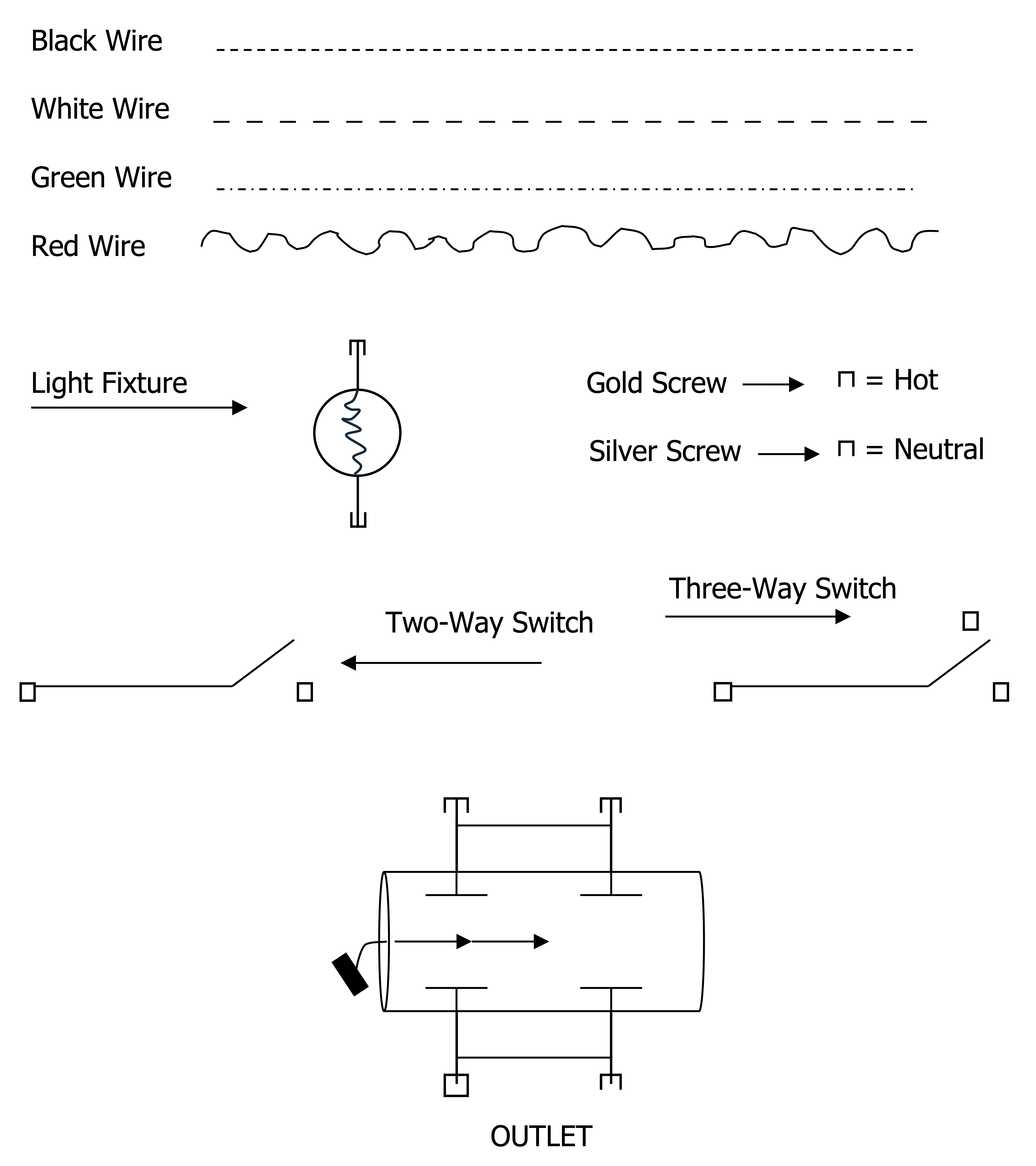
- Here are the codes we will use in this class (see page A).
- Put page A on overhead and uncover one at a time (show actual items also).
- Make sure students get the codes and the following in their notes:
- Write on board:
- Black wire = Hot wire (always hot).
- White wire = Neutral (only carries current when the load is on if wired properly).
- Green wire = Ground.
- should not carry current
- used as a safety
- will be discussed later
- Red wire = Hot
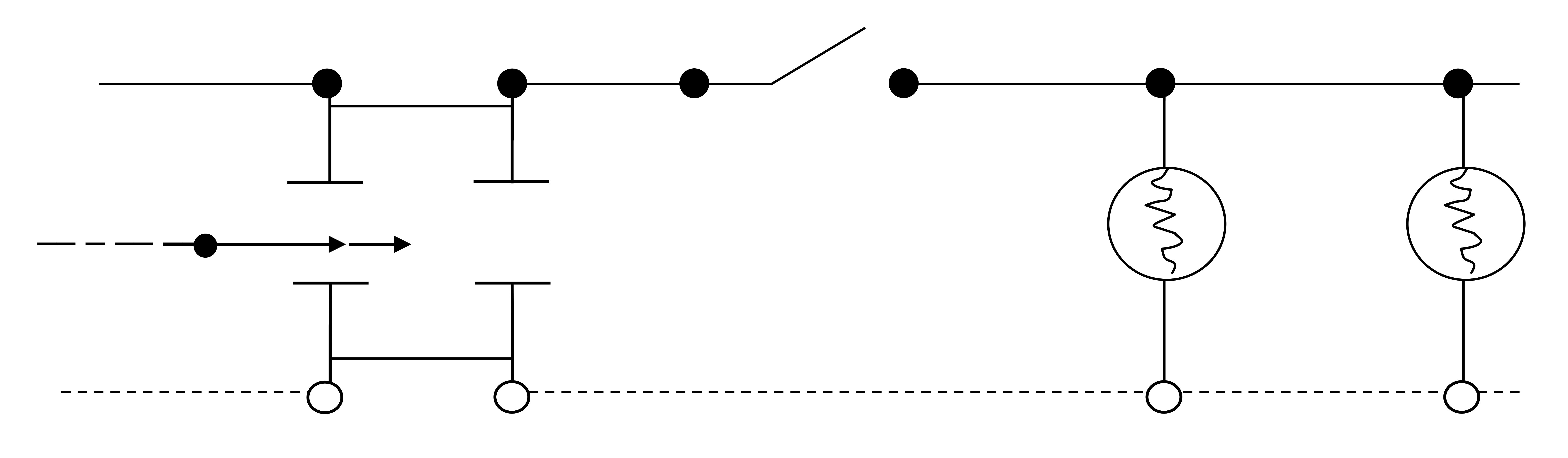
- After finishing page A, put the circuit on page Bon the board and lead a discussion on it. (Have the students draw it in their notes also.)
- What color are the wires?
- What is this?
- Why is this switch here?
- Is the outlet always on?
- Are the lights always on?
- Make sure they have the following in their notes:
- Always run the neutral directly to the loads unswitched. This should be the first step.
- Always switch the hot or black wire. We cover this in more detail in safety.
- Notice that the hot wire is on the gold terminals.
- You must have a complete circuit.
- Summary
- Have each person draw a diagram of a circuit with four lights and one switch. Two lights are always on and two are switched.
- Also have them draw a diagram of a switched light with an unswitched grounded outlet on the other side of it.
- Hint: Need three wires for part of it (red wire).
- Help individual students as needed (see solutions in the accompanying diagram).
- Trial Discussion
Problem 2. How do I select the proper fuse size for a given load, and how does a time-delay fuse work?
-
- Trial Discussion
- Why do we need to use the proper fuse size?
- What happens if the fuse we use is too little? Too big?
- What happens to a fuse when we have an overload? A dead short?
- Demonstration/Experiment:
- Show the students a cord with a dead short wired across a micro wire.
- Ask them what they think will happen.
- Plug the cord in and blow up the wire.
This was a dead short. The micro wire acted as a fuse or as the wire if it had not been fused. Place a micro wire in series with a circuit operating on an iron. - Ask what will happen.
- Turn the iron on and wire gets red hot.
- Have a student touch the wire with paper.
This is what can happen to a wire if it is overloaded and the fuse is too big (similar to 1,000 gpm through a quarter-inch hose). Time-delay fuses are made to protect a circuit from both an overload and a short circuit.
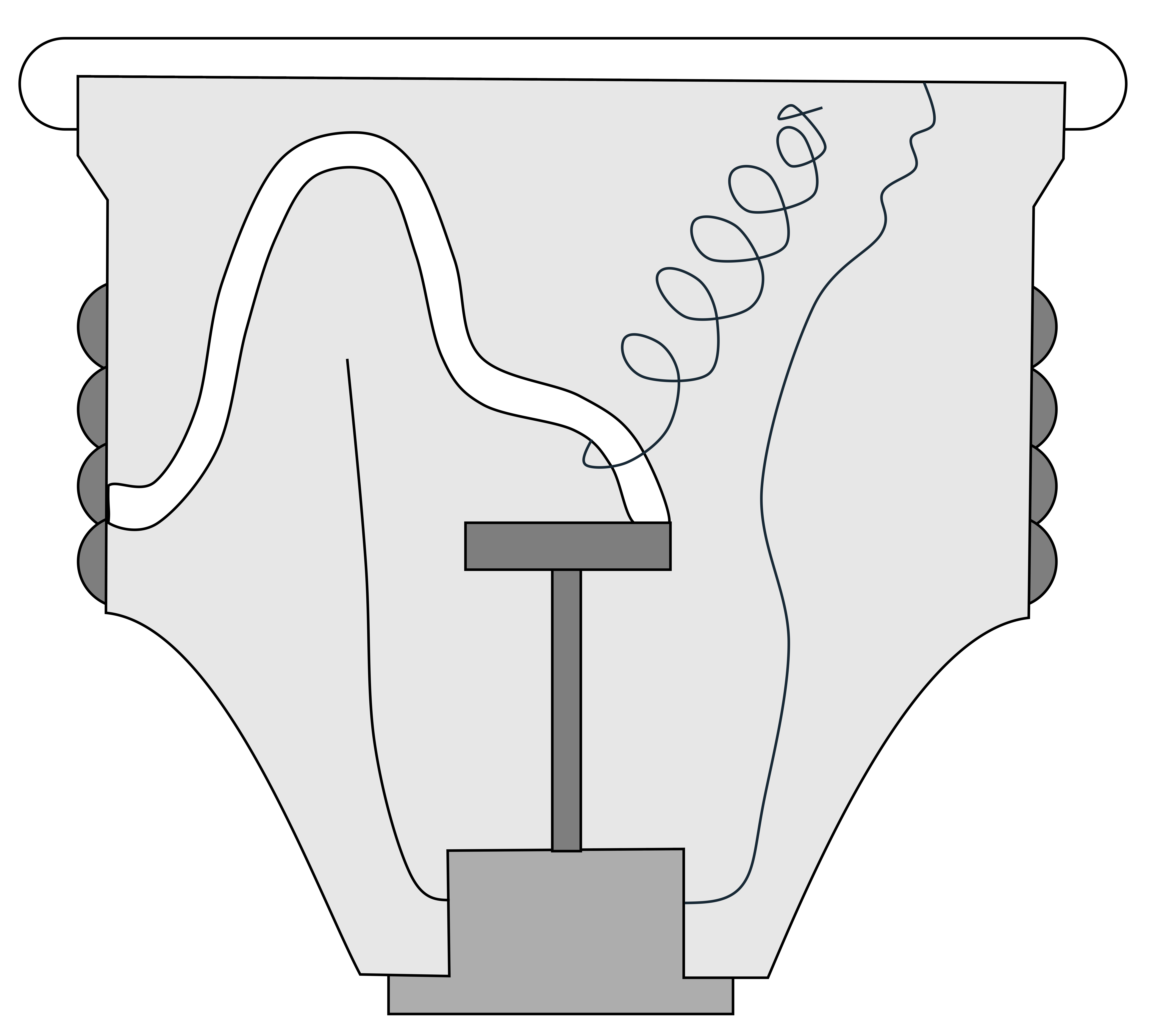
- Here’s how fuses work (put up a transparency of page C and explain).
- If overloaded for a period of about one minute, the solder melts and opens the circuit.
- The fuse handles short overloads.
- Short circuit blows the link.
Now that we know how a fuse works, how do we know what size fuse to use?
Anticipated answer:- By the load.
- V x A = W or A = W/v.
Where V = volts
A= Amps
W = Watts
Example: A 2,300-W heater at 120 v? A 20-amp fuse.
Note: For motors, figure the amps at full load and then multiply by 1.25 because 25 percent over current is allowed.
- Summary
Pull from class- With a time-delay fuse, what happens if you have a slight overload for thirty seconds?
- What happens if there is a short circuit?
- How do we figure fuse size? For motors?
- Trial Discussion
Problem 3. How do I perform wiring tasks safely?
-
- Electricity can be dangerous, but so can a car, a match, or an unprotected power take-off shaft. If used properly, they will not hurt you. Electricity is one of the safest forms of energy if used properly. If not, it can kill you. What is it about electricity that causes electrical shock or death? Volts? Amps? Watts?
- It is the current flow or amps.
1/50 amp: You can’t let go—get in notes and put on board.
1/10 amp= Death—get in notes and put on board.
You must have about 100 v to push it through, but it is the amps that kill. You could stand 100,000 v if they were forcing only 1/1,000 amp (it has been done). So if we are to prevent electrical shock, what must we prevent? - Current flow through the body.
How do we do this?
- It is the current flow or amps.
- I’m going to relate to you a true story and you see if you can figure out why it happened.
- Tell story of man on a camper who got shocked when he touched the aluminum ladder while holding a drill.
- Why? The case of the drill was hot because of a short, and he completed the circuit to ground. How could this have been corrected (in notebooks)?
- Double insulated tools (explain and show examples).
- Grounded.
- Draw the circuit of (a) ungrounded and (b) grounded, and explain how each works.
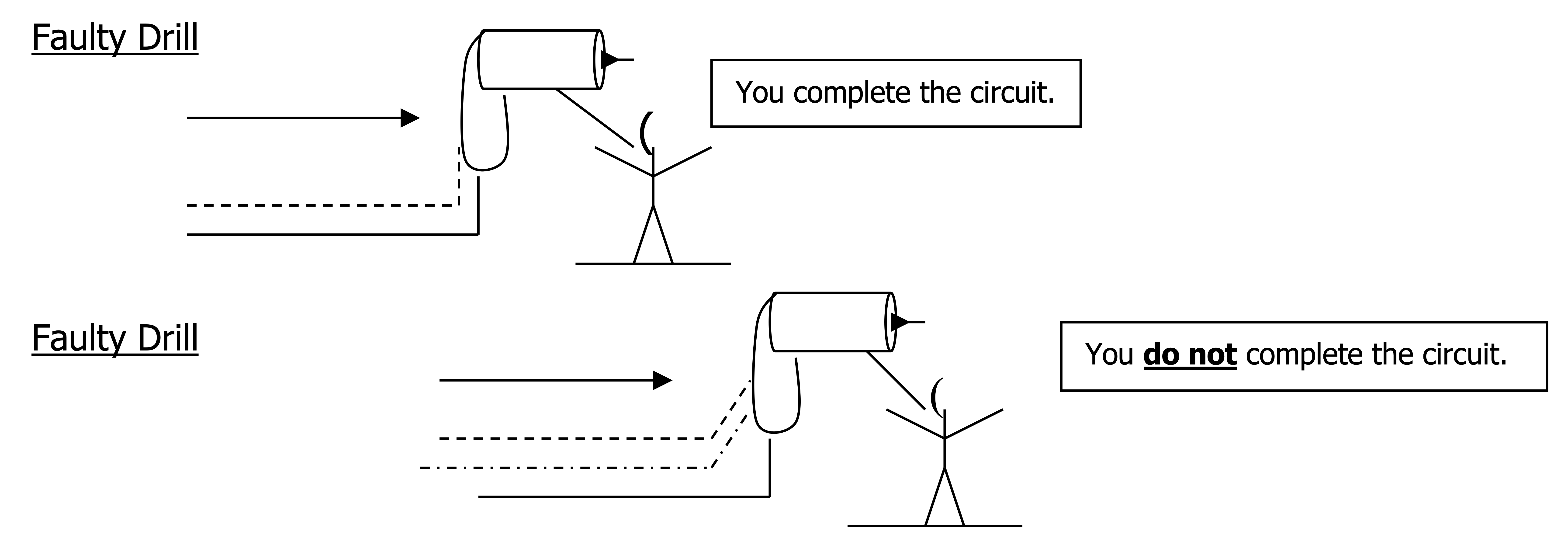
Figure A2. Figure description available at the end of the appendix. - All wiring jobs should be polarized. Put on the board: Polarity—using specific color, shape, or location of parts to identify the hot and neutral conductors of a circuit.
- We have already talked about this some (color codes for wire and screws), but let’s take a closer look at why we need to do this.
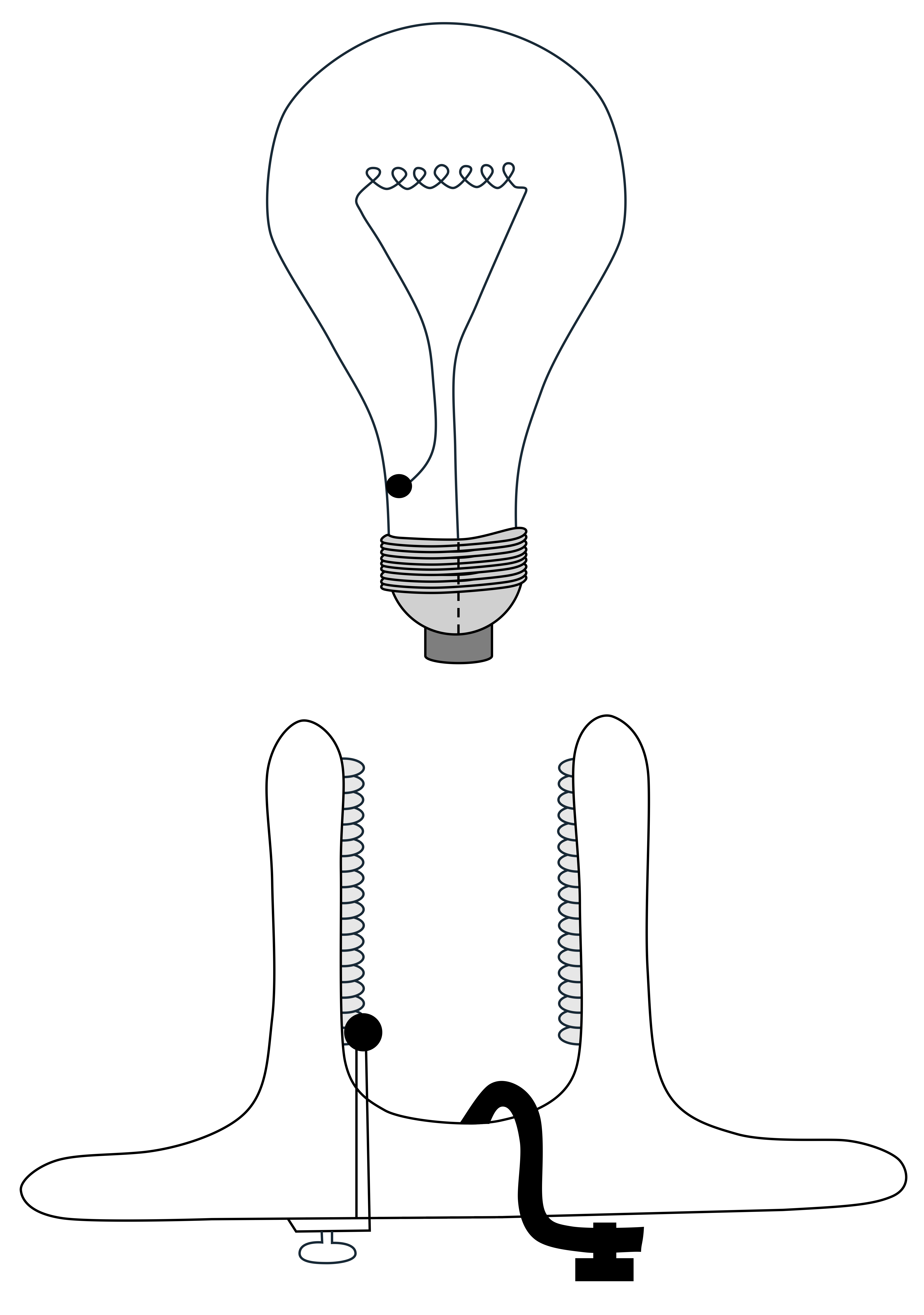
- Use page D to help explain, along with an actual light and fixture.
- Show what is hot and what is neutral.
- Show potential shock hazard if not polarized in order for it to work.
- The entire system must be polarized in order for it to work.
- Point out why switches and fuses should be in the hot wire on any load.
- When you are performing wiring jobs or making electrical repairs, what is the surest way to keep from getting shocked?
- Turn off all electricity by pulling the main fuse.
- Always make sure the power is disconnected.
- Some electricians who make repairs on live circuits say that they are safe, but it only takes one mistake.
- Wet ladder
- Dirty ladder
- Faulty insulation
- Wrong move or slip
- Summary
- If you had to take an electric shock, what would you want to make sure it was low in? How low
- amps: < 1/1,000 amp.
- How does grounding help to prevent shock?
- How does polarizing help to prevent shock?
- When you are shocked, you are actually completing an electrical ___ ?
- Circuit.
- What should you always do to a circuit before working on it?
- Disconnect it (pull main fuse).
- Let’s keep these things in mind when we are wiring.
- Give a closed-book quiz over this problem.
- Electricity can be dangerous, but so can a car, a match, or an unprotected power take-off shaft. If used properly, they will not hurt you. Electricity is one of the safest forms of energy if used properly. If not, it can kill you. What is it about electricity that causes electrical shock or death? Volts? Amps? Watts?
Problems 4 and 5. How do I wire two-way switches and lights?
-
-
- We have been studying electricity for ___ days now, but we have been doing it all on paper.
- We have been studying circuits and safety, and drawing wiring diagrams on paper, but the real test is to see if you can actually wire the real thing.
- Do you think you are ready?
- Just to be sure, let’s do an example together as a class and then you can try it on your own.
- Let’s draw the circuit on the board for a switched light (have class tell how to draw it).
-
-
-
- Now, how do we wire it? If you all will come up here, we will wire this circuit and you can see.
- See page E for needed materials.
- See page F for steps to follow when conducting the demonstration.
- Divide students into groups of about three or four, depending on the number of wiring boards available, and have them wire two lights hooked in parallel controlled by a two-way switch.
- Before the students in a group may begin wiring, they must show me a wiring diagram of the circuit.
- Supervise the wiring and help where needed.
- For all wiring projects, the students will be working on tables away from outlets. They must come to me and have me check their work before going to the assigned area to test it.
-
Problem 6. How do I wire three-way switches?
-
- Trial Discussion
- If you remember back to when we first started this unit, several of you said that you had situations where you could operate a light from two different locations.
- What kind of switch must we use to do this?
- How does it work?
- How do we wire it?
- Discussion.
- Trial Discussion
-
-
- Explain how it works.
- Draw two three-way switches and a light fixture on the board and see if students can figure out where to connect the wires (see page G). Explain why.
- Erase the first example from the board and have students diagram:
Source ➔ Switch ➔ Switch ➔ Light
and then wire it. - Check boards before they are plugged in.
-
Problem 7. How do I wire outlets?
-
- Trial Discussion
- How many of you are using multiple plugs such as this one (show one) at home so you can plug more things into an outlet?
- What is wrong with these situations?
- Circuit overload.
- Tripping hazards.
- Fire hazard, and so on.
- How could we correct these problems?
- Install more outlets.
- Here is a duplex (will take two plugs) outlet. Do you notice anything different about the screws? Yes—it has a green one. What goes there? (The ground.)
- Let’s see if we can wire outlets.
- First, I want you to show me a wiring diagram for the following circuit (one for each group) and then you can wire it (see page H ). Source ➔ Switch ➔ Outlet ➔ Outlet
- You can use your notes if you need to. You may want to look back to see how to indicate an outlet on paper.
- Trial Discussion
APPROVED PRACTICES
- Draw a wiring diagram before wiring.
- Use proper symbols when making wiring diagrams.
- Protect all circuits with a fuse or circuit breaker with hot wire.
- Always switch the hot wire.
- Always run a neutral wire to the load unswitched.
- Determine fuse size from this equation: volts x amps = watts.
- Polarize all circuits.
- Ground all metal-cased appliances and tools; use ones that are double encased.
- Always pull the main fuse before making wiring repairs.
- Put six inches of wire into each electrical box to work with.
- Put wire around screw in the direction in which it will be tightened.
- Use wire nuts to connect wires together, or solder them.
- Always make connections inside a metal box.
- If using a wire as a hot wire, paint two inches on each end black.
GENERAL PRINCIPLES
- Electricity is created by the flowing of electrons.
- Electrical pressure known as volts causes the electrons to flow.
- A conductor allows electrons to flow through it.
- Copper is a better conductor than aluminum.
- An insulator does not allow electrons to easily flow through it.
- An amp (ampere) is a measure of current flow.
- An ohm is a measure of electrical resistance.
- Electrical resistance causes heat.
- Resistance is affected by a. Material size b. Size c. Length
- Volts/ohms = amps or amps x volts = watts.
- A watt is a measure of electrical power. Watts= amps x volts.
- The larger the wire gauge number is, the smaller the wire is.
- One thousand watts operated for one hour equals one kilowatthour (kwh).
ELECTRICITY TEST
Name:
TRUE OR FALSE
Directions: Put a T in the blank before the item if it is true; put an F if the statement is false.
1. Less than one-half amp can kill you if the voltage is high enough to push the current through your body.
2. A large wire can carry more amps at a given voltage than a small one.
3. A large wire has a larger wire gauge number than a small one.
4. When a metal-cased electrical tool is not grounded and the case becomes “hot,” the person holding it completes the circuit if he or she is grounded.
MULTIPLE-CHOICE
Directions: Select the best answer and place the letter in the blank to the left of the statement or question.
5. When installing a switch in a simple lamp circuit, which wire should be attached to the switch?
-
- white
- green
- black
- yellow
6. Metal materials in which electricity flows easily are called:
-
- transformers
- insulators
- short circuits
- conductors
7. The flow of current is measured by:
-
- a voltmeter
- an ammeter
- an ohmmeter
- a micrometer
8. Using color, shape, or position of electrical circuit parts to distinguish the hot from the neutral parts of the circuit is called:
-
- harmonizing
- labeling
- grounding
- polarizing
9. Heat is generated from wires because of electrical:
-
- resistance
- conductivity
- magnetic fields
- insulators
10. The longer an electrical wire is, the greater the ___ will be.
-
- volts
- ohms
- amps
- watts
11. When making wiring repairs, the best way to keep from getting shocked is:
-
- Never touch the hot wire while you are grounded.
- Use rubber gloves.
- Pull the main fuse.
- Stand on wood (dry).
MATCHING
Directions: Put the proper letter from the selection of letters at the bottom in the blanks of the numbers below. There is only one answer for each blank, and you should not use the same answer twice.
12. Neutral wire color
13. Hot wire color
14. Neutral screw color
15. Ground wire color
16. Hot screw color
-
- green
- black
- blue
- gold
- silver
- orange
- white
FILL-IN
Directions: Fill in the blanks with the best word or words.
1 7. Electric companies charge for electrical energy in units of .
18. Electrical pressure is measured in .
19. Electrical resistance is measured in .
20. The amount of electrical flow of current in a circuit is measured in .
21. Electrical power is measured in .
PROBLEMS
Directions: Work the following questions. Show all work and circle your answer for full credit.
22. & 23. An electrical motor runs for twelve hours. The motor is 120 volts and pulls 115 amps.
- How many watts is the motor using?
- How many kilowatts is the motor using?
- How many kilowatt-hours are used in the twelve hours?
- If you pay fourteen cents for each kilowatt-hour, how much does it cost to use it for the twelve hours?
24. Problem 2. What size fuse should be used to protect a 2,200-watt heater at 115 volts?
PAGE A
PAGE B
PAGE C
PAGE D
PAGE E
Materials Needed for Demonstration of Switch and Light
- 5″ + of 14-2 wire
- Pocket knife
- Wire strippers
- Wire pliers and cutters
- Needle nose pliers
- Wiring board
- Wire nuts
- Cable clamps
- Screwdriver
- Hammer
- Switch
- Light fixture
- Light bulbs
PAGE F
Steps and Key Points
- Disconnect power.
-
- Pull main fuse usually.
- Strip wire.
- Use knife.
- Use wire stripper.
- Cut wire.
- Long enough for six inches into each box.
- Attach cable.
- Use hammer and screwdriver to tighten.
- Attach wires.
- Follow color coding.
- Put each wire around the screw in the direction in which the screw will be tightened.
- Don’t tighten too tightly or you will have trouble the next time.
- Make connection of wires using wire nuts.
- In class, let instructor check before proceeding.
- Push switch and wire into outlet box.
- Fasten switch to the box with screws.
- Replace switch plate.
- Fasten fixture to box.
- Turn power on.
- See if it works.
PAGE G
PAGE H
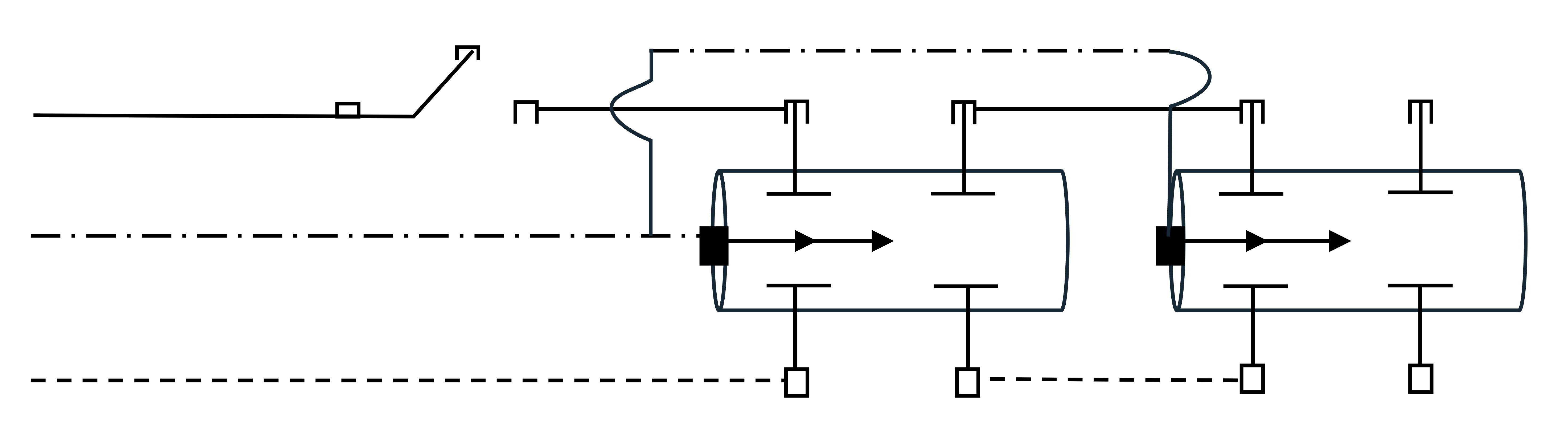
Figure Descriptions
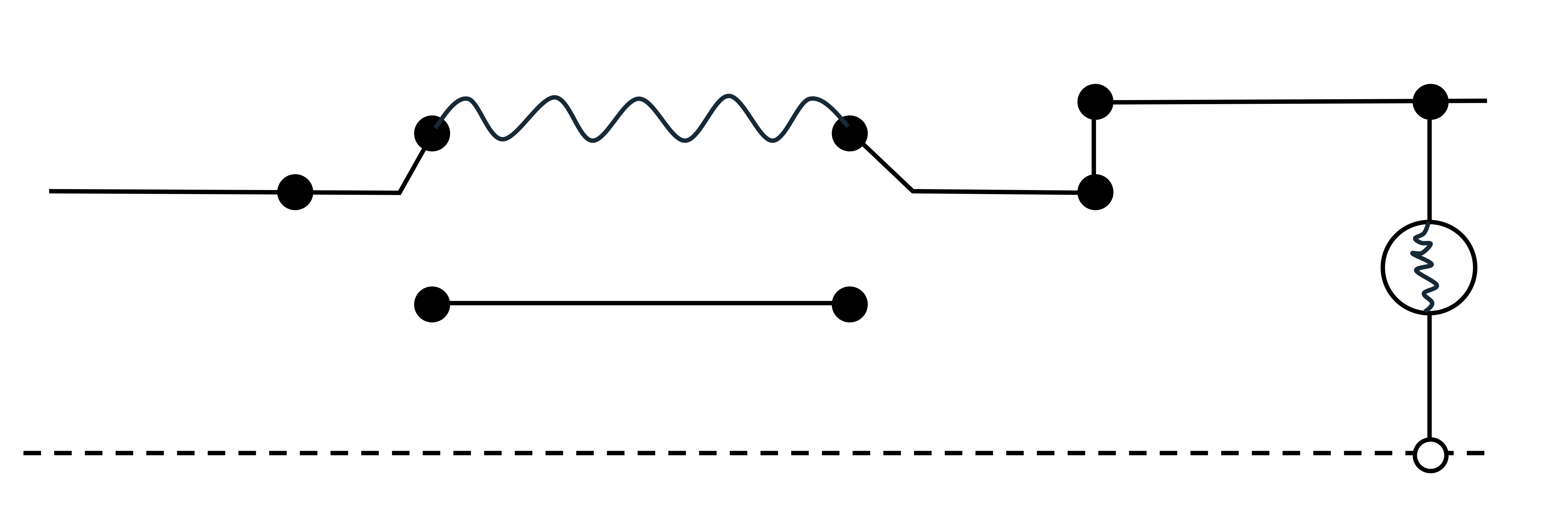
Figure A1: Top: Diagram of a circuit with four light bulbs and one switch. All four bulbs are connected in parallel across two horizontal lines. There is a single switch located on the upper connection line. Bottom: Circuit diagram with a coil, switch, lightbulb, and unswitched grounded outlet. The circuit starts with a single switch connected to a coiled wire (inductor) at the top of the diagram. The coiled wire connects to a single light bulb (resistive load) placed in series along the circuit path. After the light bulb, there’s a break in the line, which leads to the outlet. The outlet is connected to the ground line, completing the circuit.
Figure A2: Top: Diagram of a “Faulty Drill.” The image depicts a person holding a drill with an exposed wire with a label stating “You complete the circuit.” Bottom: Diagram of a “Faulty Drill.” The image depicts a person holding a drill with no closed path through the person with a label stating “You do not complete the circuit.”
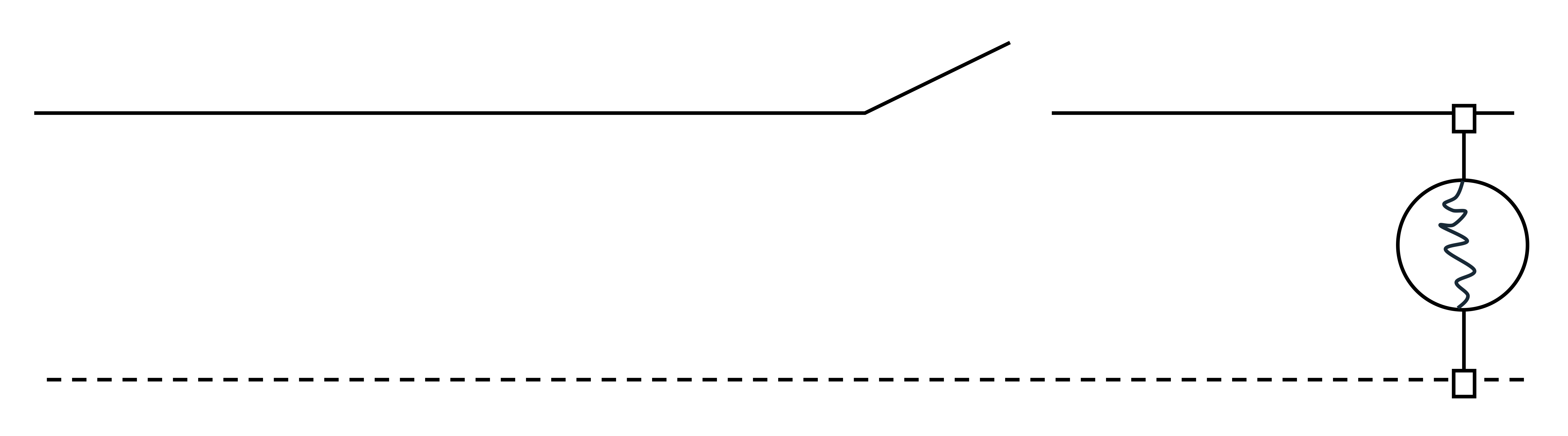
Figure A3: A diagram of an electrical circuit with a single switch and light bulb connected in series. Starting on the left, the circuit starts with a switch located on the upper line. On the right of the switch is a lightbulb that completes the circuit by connecting to the lower dashed line (ground).
Figure A4: A three-way switch, with one screw on the left and two upper and lower screws on the right. The switch is connected to the left and upper screw.
Figure A5: A diagram showing different symbols for different colors of wires. The black wire is a dashed line, the white wire is a longer dashed line. The green wire is a line that alternates between dashes and periods, and the red wire is a squiggly line. A light fixture is shown on the left with symbols for a gold and silver screw. Two way switch has two screws and a three-way switch has three screws. The last picture on the bottom shows an outlet with gold screws connected to the hot wire and silver connected to the neutral wire.
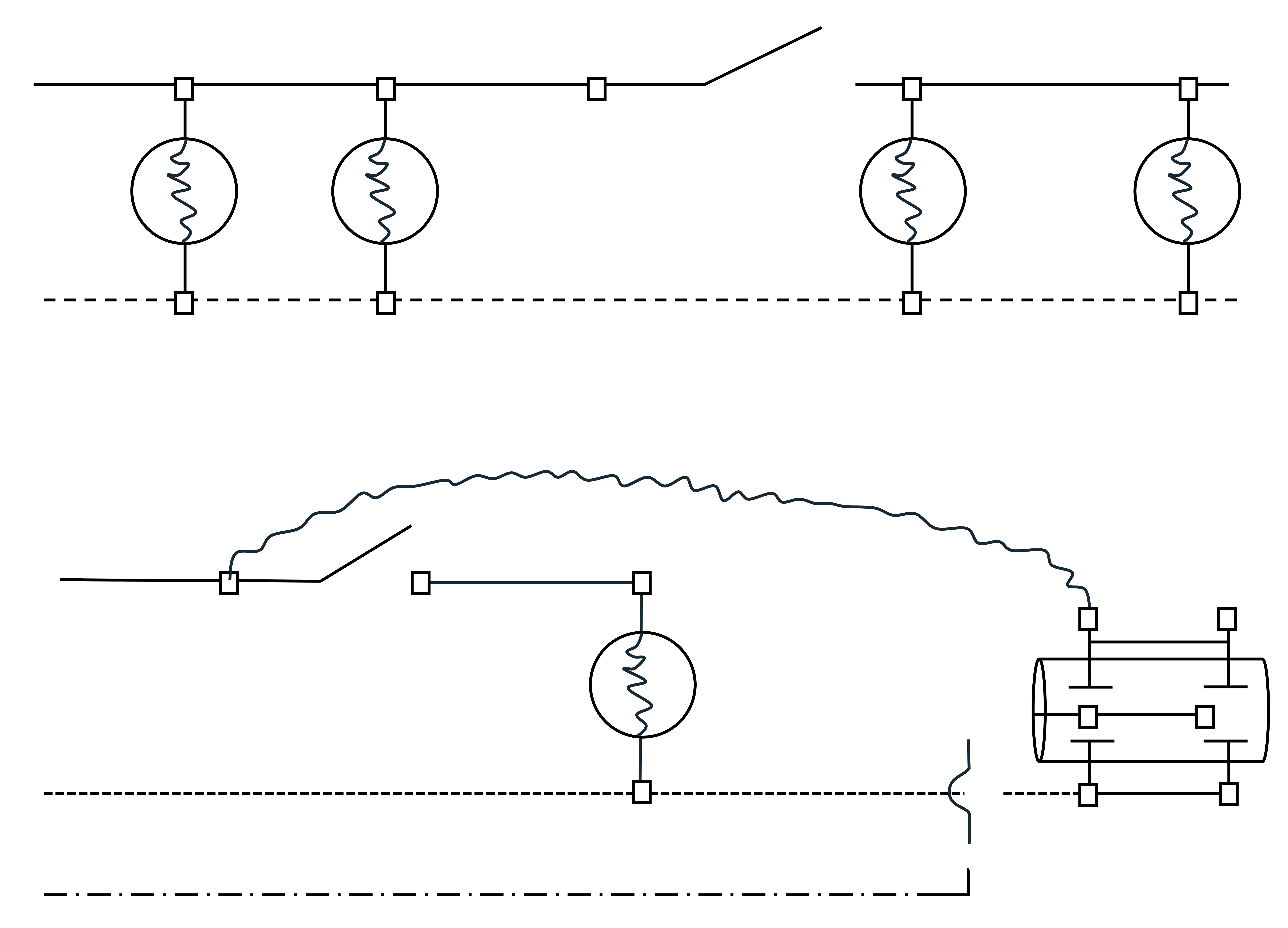
Figure A6: A circuit diagram containing switches, light bulbs, and capacitors in series and parallel arrangement. Starrting on the left, there are two parallel capacitors. Followed by a two way switch and two parallel lightbulbs. There is a dashed line at the bottom representing ground and arrows pointing to the right indicating direction of current flow.
Figure A7: A cross-sectional diagram of a time-delay fuse. The fuse consists of a cylindrical casing with two metal terminals on either side. Inside, there is a coiled spring connected to a conductive strip, which is curved. An element is in the center connected to a plunger mechanism.
Figure A8: A light bulb and a related circuit component. The upper part displays a light bulb with a coiled filament inside, encased in a glass envelope, and a threaded metal base for electrical connection. Below the bulb, a schematic of a circuit is shown. It features two coiled components connected by a wire at the base, resembling the terminals of the light bulb.
Figure A9: A circuit diagram that includes an inductor switch, and light bulb. The circuit begins with an inductor on the left, represented by a coiled line. Next, is a switch located between the inductor and light bulb. There is a dashed line (ground) at the bottom that completes the circuit.
Figure A10: A circuit diagram that has a switch with batteries. It starts with a two-way switch on the left. Followed by two batteries in parallel, there is a looped connection at the top connecting the batteries back to the switch on the left side of the circuit, completing the path.
